Sunday, October 28, 2012

Arduino mp3 player (II)


The SD structure

In this post I'll try to explain a little the code of  our 'Jukebox' Arduino hearted .
The main problem I found for this project, was the limitation SD library, with reduced FAT which only allowed the names in 8.3 format.
The solution was to create a small catalog in a text file from which to read the entries.

The directory structure on the SD has the following format:
raiz
 +-artistas.txt
 +-[ARTIST01]
 |   +-album.txt
 |   +-[ALBUM01]
 |   |   +-track.txt
 |   |   +-track001.mp3
 |   |   +-track002.mp3
 |   |   .....
 |   |   +-track0nn.mp3
 |   +-[ALBUM02]
 |   .......
 |   +-[ALBUMnn]
 +-[ARTIST02]
 .....
 +-[ARTISTnn]

This means there are three levels: artist, album and track. Each level has a text file with the catalog entries (a line of text for each artist, album or song).
The names of the folders and files must be such as are in the scheme (you can always change the code).
It's a bit cumbersome to create the card, but ... worthwhile. I used a program that makes it much easier MP3Tag, enabling export to text tracks of a directory and rename mp3.


Monday, October 22, 2012

Arduino MP3 Player (I)


I present this new Arduino project: A full MP3 player based on Arduino.
As you can see in the photo, the idea was to build a standalone player, in the style of antique radios or 'tapes', in the age of Iphones ....
The player uses a small module based on the VS1002d chip (now discontinued, but who had a drawer). The module in question I bought at  Futurlec . Currently you can get similar modules on ebay for a bit more than 10$, although the chip is the VS1003 o VS1053. You can also use a SparkFun MP3 shield, but significantly more expensive (this shield already includes an SD slot).
The three chips are quite compatible in terms of programming, and indeed almost all initialization the I have taken from the library to the SparkFun MP3 Shield ;-)

Wednesday, September 12, 2012

Arduino light organ (III)


<< Arduino light organ (II)- The circuit

WARNING: In this part is used mains voltage, which can carry risks. If you do not have enough experience or not you think trained, best uses few leds low voltage and evitate a scare. The author is not responsible for any damage caused by not taking proper security measures.

For the power stage I used  triacs of type BT137 controlled by optocouplers MOC3041. Depending on the power you need to control, you can change the type of TRIAC less powerful one (or more ...).

The optocouplers MOC3041 internally contain a control circuit for triggering the zero crossing, the triac is always close to zero voltage pass avoiding interference.
You can use other types of optocouplers respecting the circuit recommended by the manufacturer.


The scheme:
Power stage for Arduino organ light


And this appearance when mounted (in my case the stage is 4 channels)

Power stage of Arduino light organ

Note that a box is mounted on suitably isolated. The heatsinks are Triacs for high continuous loads (in this case support 8A, allowing about 1500W per channel).

The result:


Have fun ....

Arduino light organ (II)


<< Arduino light organ (I) - Introduction             Arduino light organ (III) - Power stage >>

Obtaining the signal

As I mentioned in the previous post, in my case I am going to use a microphone as a signal source, this eliminates the need to connect directly and provides more freedom of movement.

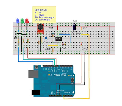
I've used a Dealextreme module, the SKU: 135533, a sound detector module with digital output and analog. Here we use the latter.
As the level of the signal delivery is very small, I used an ancient u741 (but functional) that had a drawer, to adjust the input signal to the Arduino.
It is also possible to directly use an electret microphone, but we have to amplify it properly (you can find plenty of schemes on the internet), or use a module, and amplified as this


The scheme: (click images to enlarge):

Arduino light organ scheme

And the assembly:

Arduino light organ assembly

Arduino light organ (I)


Introduction

Those who have a few years as I, recall that back in the 1980s, in any disco or party was mandatory the psychedelics lights, i.e. those lights ranging to the rhythm of the music. It could be a single light or more, normally 3 that varied with bass, middle and treble of the music.
It could be achieved already made (very expensive for the time), on Kit (the mythical SalesKit) either make you them yourself.

Well because I was a fan of lights (and parties) and I built a couple of them, the first for more than 30 years (Yes, Yes,...) in a great box made of plywood, but Unfortunately a few months ago ended in the trash ..

The second of some 30 years ago... still alive and kicking...

Psychedelic light organ Elektor 1982

Taken from the wonderful magazine Elektor March 1982

Elektor Magazine March 1982

Well after this story chive Grandpa, let's see how to emulate those mythical lights with our beloved Arduino.
The idea is to use a sound source, in my case a microphone, bring it into line with the level of the entries of the Arduino, apply a FFT process to separate the different frequencies, grouping these into three channels (bass, mid and treble), and depending on which exceed a certain level, activate the outputs of the Arduino.
These outputs can attack some leds initially, but to make it more authentic then use a triac output stage with some bulbs

Are you interested? read in the next post ...       Arduino light organ (II) - The circuit 

The video to whet your mouth ......


Sunday, September 2, 2012

Arduino RGB led managed by remote control

Taking advantage of the previous post, we are going to add an IR receiver to the circuit so that we can vary the color and brightness of the led with a remote control of Dealextreme, which is perfect for the project. The controller in question is the SKU: 47019, a very cheap remote control that comes with battery included:

RGB IR Remote control

To get the Arduino detected it, will use a TSOP 1738 or similar type infrared receiver (in my case I have a 1736 and works equally although command uses a 38KHz carrier).

Friday, August 24, 2012

'Rainbow' RGB Led with Arduino


Well, let's start with a 'dumb' for begin.
The idea is that a RGB LED simulate the effect  'Rainbow' as some by themselves (RGB LED vary automatically its color, passing by the colors of the rainbow).
In my case I´m going to use a RGB LED Dealextreme. This 5 Watt-led produces a large amount of light and it is very robust.
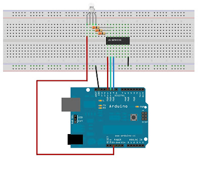
As the arduino can not give a very large current for its output, i´ll use a ULN2003 driver to not load too.


This is the assembly:

RGB Led with Arduino

Welcome


Hi all
Start with this blog to share my experiences in electronics, and all the possible information you can provide.
The idea is to post on all my experiences with Arduino developments.
Until now I worked more with PICS, but I discovered the world of Arduino and I have to say that I liked it.
For those who do not know, is an open platform for which you can find plenty of material, both hardware and software.
By the way I'm also fond of buying Dealextreme, and lately has countless gadgets for our developments, and I will be showing.
Gradually things I will be showing on this platform: links, libraries, and all you can.
But hey, less roll and let the subject .....


Arduino Chromatic Clock, with Steampunk style

Arduino Chromatic Clock, with Steampunk  style Need a unique gift for Christmas? ... This watch unlike normal, uses colors instead of...